
Image result for sheet metal manufacturing drawings Service design, Metal manufacturing, Metal
This chapter explains how to create sheet metal drawings. Gauges for sheet metal are presented along with bend radii, flanges, tabs, reliefs, and flat patterns. Sheet Metal Drawings Figure 13-1 shows a 3D solid model of a sheet metal part and a dimensioned orthographic drawing of that part. The orthographic drawing was created from the 3D model.
Share more than 67 sheet metal drawings for practice latest nhadathoangha.vn
For a slot or hole > 1" diameter then the minimum distance "D" = 2.5T + R (see fig. "C") Form height to thickness ratio - To determine the minimum form height for sheet metal use the following formula: D = 2.5T + R (see below) The height can be less but it required secondary operations and is far more costly.

sheet metal drawings for practice pdf lineartdrawingsaestheticbutterfly
2D drawings serve as the bedrock for manufacturing industries, acting as the blueprint for every process, including sheet metal fabrication.These technical drawings encapsulate the design intent, detailing every aspect, from dimensions and tolerances to material specifications and finish requirements. However, to fully leverage these drawings and achieve immaculate sheet metal parts, one must.

Sheet Metal Drawings For Practice Pdf Warehouse of Ideas
Now let's use SolidWorks to create a sheet metal transition. 27. Start a new inch part and create a new Sketch on the front plane. Constrain the geometry and dimension as shown. The rectangular geometry on the right side of the sketch is used to create and center a gap in the sketch geometry.

sheet metal drawings for practice pdf lineartdrawingsaestheticbutterfly
Exercise 2. Drawing of Rim Figure 49 Wheel Assembly Exercise 3. Drawing of Shaft Figure 50 Annotations Exercise 4. Drawing of Sheet metal part Figure 51 Sheet metal Exercise 5. Drawing of Sheet metal part Figure 52 Multibody sheet metal TOPICS: Drawings Tools View Palette Model View Section View Section View Assist
sheet metal drawings for practice pdf photographyascontemporaryart
TS_BP_SWX_Sheet_Metal.pdf is a best practice guide for sheet metal design using SOLIDWORKS. It covers topics such as sheet metal features, forming tools, flat patterns, and drawings. It also provides tips and tricks to optimize your sheet metal designs and avoid common errors. Learn how to create efficient and accurate sheet metal parts with this helpful document.

Sheet Metal Drawings For Practice Pdf Warehouse of Ideas
drawings and Manufacturing. Remember to do all design work in the bent state or generic, so your model will be correct. 8. Create drawing, showing bent and flat states on the same page. Show the dimensions on the bent part, create ordinate dimensions on the flat state. Sheetmetal Pocket Demo Page 3 of 5

sheet metal drawings for practice Much Indeed Forum Image Archive
Do you want to practice your sheet metal skills in SOLIDWORKS and prepare for the CSWPA-SM exam? Download this free sample exam and test your knowledge of sheet metal design, modeling, and drawing. You will find detailed instructions, questions, and solutions for each part of the exam.
Sheet Metal Drawings For Practice Pdf Aesthetic Drawing
How to take this sample exam: The questions in this sample exam give an indication of the type and difficulty of the questions on the real exam but ARE NOT MEANT TO REVEAL ALL THAT IS COVERED ON THE TEST. For a list of topics covered on the CSWP-SMTL exam, please go to www.solidworks.com/cswp.

Sheet Metal Practice Drawing Sheet metal drawing, Drawing practice, Mechanical design
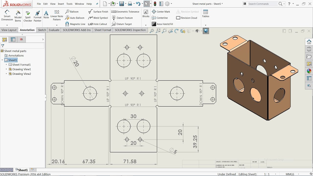
Drawings of Sheet Metal Parts. When you create a drawing of your sheet metal part, a flat pattern is automatically created. Drawings of sheet metal parts can also contain views of the bent sheet metal part. You can create *.dxf files of sheet metal flat patterns without creating a drawing.

i want sheet metal part drawings to practice iam not able to get from google can anyone pls help
5 • Blend Create a sheet metal wall by blending several sections sketched in parallel planes as shown in Figure SM.10. Figure SM.10 Base Feature, Blended Wall • Flat Sketch the boundaries of the wall (Fig. SM.11). Figure SM.11 Feature, Flat Wall • Offset Create a wall that is offset from a surface (Fig. SM.12). Figure SM.12 Base Feature, Offset Wall.

sheet metal drawings for practice pdf Alyse Britton
The purpose of this GoProto Sheet Metal Design Guide is to help you de ne the speci cs so that your designs are ready to go in production with us in such a way that theoretical versus actual is minimal and your features match available processes. This will help us make your parts fast, make them right and make them inexpensively.

olidWorks Sheet metal Exercise Basic Features Sheet metal drawing, Sheet metal, Metal sheet design
Defining the Sheet Metal Parameters This task shows you how to configure the sheet metal parameters. 1. Click the Sheet Metal Parameters icon . The Sheet Metal Parameters dialog box is displayed. 2. Enter 1mm in the Thickness field. 3. Enter 5mm in the Default Bend Radius field. 4. Select the Bend Extremities tab.

Percepire prova Antologia sheet metal drawings mantenere aggrovigliamento Treno
Experimental Analysis for Defining Forming Limit Diagram for Thick Sheets. Atanas Kochov. In this paper a combined procedure to determine the forming limit diagram (Keeler-Goodwin diagram) for thick sheets is proposed. It is defined for cold rolled steel sheet Č0147 (RSt 13 DIN 17006) with thickness of 5 mm using two different criteria.

Sheet metal drawings for practice Mechanical Engineering GrabCAD Groups
CONVERTING TO SHEET METAL Sheet Metal Conversion Imported Geometry to Sheet Metal Adding Rips Insert Bends Converting Cones and Cylinders Convert to Sheet Metal Exercise 14: Importing and Converting Exercise 15: Unrolling a Cylinder Exercise 16: Converting to Sheet Metal Practice Exercise 17: Convert with Rips

sheet metal drawings for practice Jeffrey Cherry
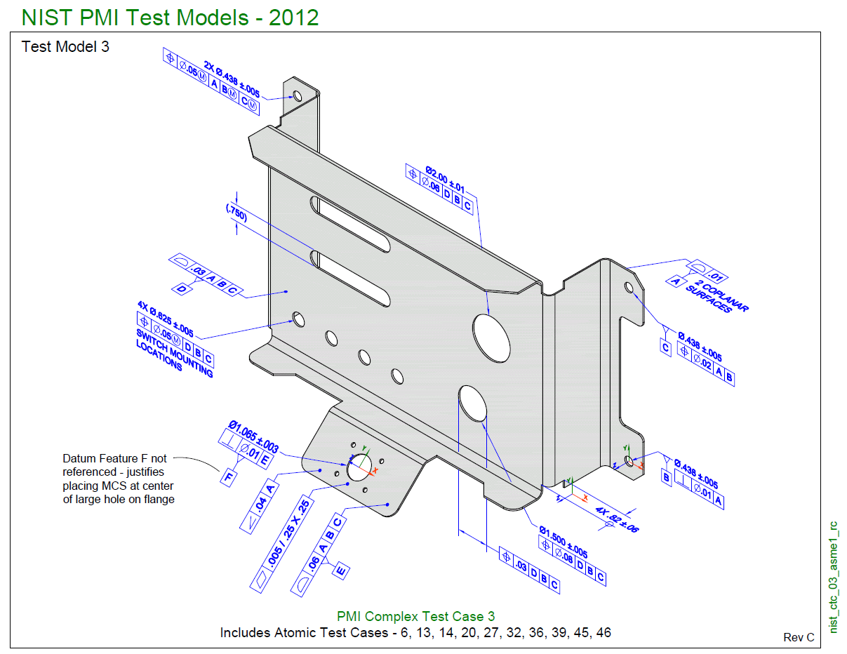
A fully dimensioned sheet metal drawing includes dimensions for all bends, holes, countersinks, flanges, and other formed features (such as hems and curls, ribs, dimples, etc…). It is a best practice to dimension to virtual intersection points and show included bend angles. This ensures that your drawing is universally interpret-able (with no.